Top Site mapHelp Site mapHelp | |
 Category TopOverview of This FunctionRegistering Custom Paper TypesChanging the NameChanging the Basis WeightChanging the SizeChanging the Finishing TypeChanging the TypeChanging the ColorSetting the Second Side of Two-Sided PageAdjusting the Creep (Displacement) CorrectionChanging the Fiber DirectionAdjusting the Level of Curl CorrectionAdjusting Fan Level for Paper SeparationAdjusting Paper Conveyance for 2-Sided Printing
 Adjusting the Image PositionCorrect Image MisalignmentAdjusting the Skew Correction Level of the Fed PaperCorrect Distortion (Parallelogram)Correct Distortion (Trapezoid)Adjusting the Zoom Ratio of the Image
 Adjusting Left Edge Alignment of the ImageAdjusting Lead Edge Alignment of the ImageAutomatically Correcting the Back Side Lead Edge Alignment of the ImageAdjusting Front/Back Side Edge Alignment of the Image by Scanning the Guide SheetAdjusting the Lead Edge/Tail End MarginsAdjusting the Total Amount of TonerAdjusting the Secondary Transfer VoltageAdjusting the Secondary Transfer Antistatic BiasAdjusting the Image Clear Level of the ITB (Intermediate Transfer Belt)Adjusting Secondary Transfer Belt SpeedAdjusting the Gloss and Fine BlackAdjusting the Saddle Stitch PositionAdjusting the Saddle Stitch Fold PlacementAdjusting the Saddle Fold PlacementAdjusting the Position of Punch HolesChanging the Tail End White Patch CorrectionDisabling Tail End Toner CorrectionAdjusting the Primary Transfer VoltageAdjusting Lead Edge Secondary Transfer VoltageDeleting Custom Paper Types
 (Settings/Registration).

|
NOTE
|
|
If the image position varies greatly, the accuracy of correction may be improved by printing several test pages and using an average of the measured length.
|


|
IMPORTANT
|
|
When you open the screen again after you close the screen by pressing [OK], the values on screen are returned to '0'. However, the adjusted value is still effective in each Total field. If you repeat the step, check the length of 'i' on the new test page and enter the new value.
|
|
NOTE
|
|||||||||
|
To restore the accumulated value, press [Restore Initial Settings].
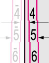
You can also correct the image position by using the value of register marks shown below. Check whether the center line of the register mark and the edge of the test page are aligned, and adjust the image position as follows:
If the center line of the register mark overlaps the edge of the test page exactly, it is unnecessary to adjust the image position.
If the center line of the register mark is outside the edge of the test page (the center line of the register mark is NOT printed), check to see which register mark's number the test page line is next to, and input the positive value.
If the center line of the register mark is inside the edge of the test page, check to see which register mark's number the test page line is next to, and input the negative value.
|
| Copyright CANON INC. 2015 | Disclaimers CopyrightTrademarksThird Party SoftwareOffice LocationsUSRM2-5983-00 CopyrightTrademarksThird Party SoftwareOffice LocationsUSRM2-5983-00 |
|---|
 Expand All
 Collapse All
 Search options